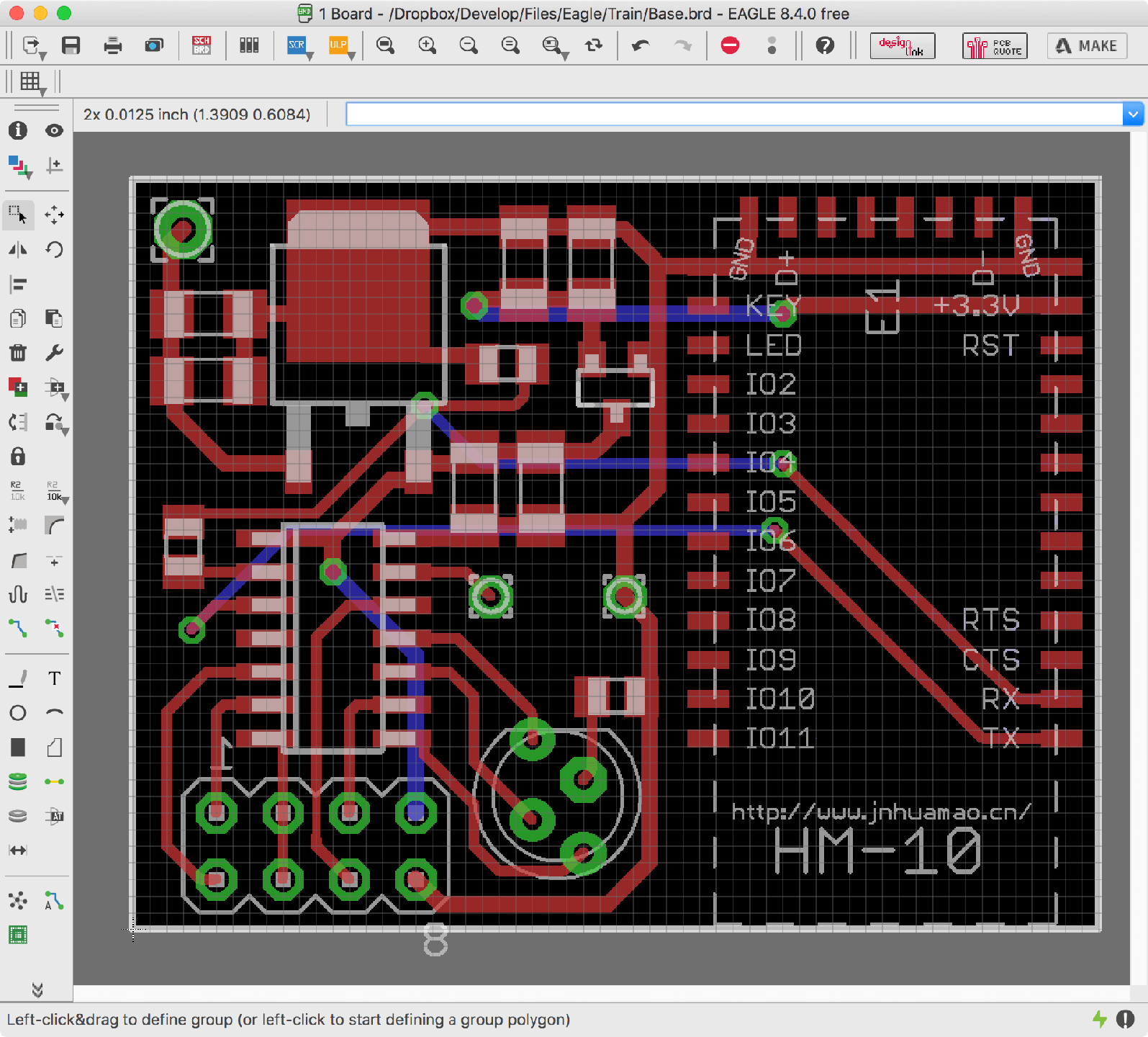
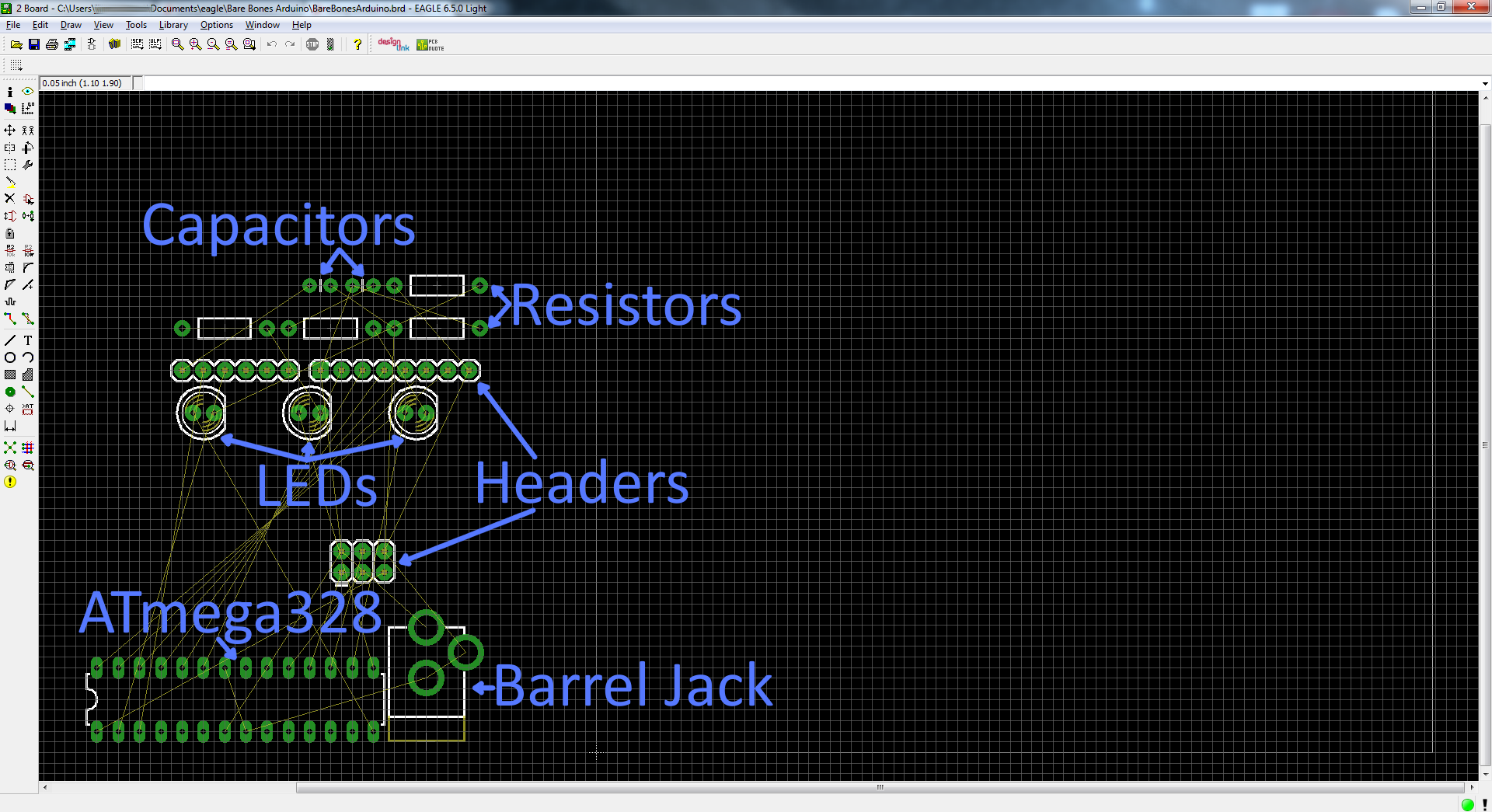
Windows edition does not require installing. Run directly from a folder. Please note, this build only works on Windows 7 or later. OS X version requires macOS 10.9 or later
|
|
Printed Circuit Boards (PCBs) are backbones of electronic devices and equipment. The increasing density of circuits and decreasing size trend of electronic products lead circuit boards to develop into higher complexity. Holes or vias, responsible for electrical connections between layers and corresponding functions a board will implement according to design requirement, won't effectively work unless they are suitably designed or manufactured. For unsuitable manufacturing, it can be easily solved by selecting a reliable PCB manufacturer. The solution to the other issue, that is, unsuitable design, depends largely on circuit board design engineers who have to create integrated and reliable design files based on which PCB fabricators carry out manufacturing.
It's believed that NC drill file generation has been plaguing most PCB design engineers for a long time. Therefore, it's necessary to summarize design guidelines based on leading PCB design software.
NC drill file, short for numeric control drill file, refers to a type of file regulating all the information concerning hole or via drilling requirement including tooling size, hole size and location. A sample NC drill file is shown below;
Canvas and Unit Setting PCB Tools Layers and Objects Tool Layer Manager Ratline PCB Net Board Outline Route Tracks Copper Pour Solid Region Design Rule Check Footprint Attributes Design Manager Import Changes Panelize Layout PCB Without Schematic PCB Preview 3D Model Manager PCB Information PCB Modules Generate Fabrication File(Gerber) Export BOM Export Pick and Place File Export DXF Order PCB. The pcb file extension is also related to Microsoft PowerPoint, a worldwide most popular powerful tool you can use to create and edit dynamic and great-looking presentations. This type of pcb file are used to store application settings data. The default software associated to open pcb file. The PCB file which is being opened is infected with an undesirable malware. The computer does not have enough hardware resources to cope with the opening of the PCB file. Drivers of equipment used by the computer to open a PCB file are out of date. The.pcb file extension is also used for ACCEL or Protel printed circuit board files, P-CAD database files, PC-Doctor files, Broderbund Print Shop business card files and PCB Layout check design rule template files. Update info Upload example file PCB file openers, viewers, etc. These apps are known to open certain types of PCB files. Then open your other PCAD schematics and add them to the Sheet one file using the Cut & Paste options. Once cleanup is complete, generate a netlist. Open the Accel EDA PCB editor, and got to Library setup. Clear what's there and set it to your library file. Now, open your PCAD PCB file.
It's of significant necessity for PCB design engineers to create NC drill files since a lot of trouble can be avoided when PCB files are converted into NC drill files and Gerber files. Nevertheless, the factual situation is that a number of engineers tend to send PCB files directly to PCB manufacturer without converting them into NC drill files or Gerber files. They have been used to finishing PCB design files or exporting the design files from PCB cloning software and sending them to circuit board manufacturers.
The ordinary workflow is that after receiving PCB design files, board fabricators have to transform them into NC drill files and Gerber files before manufacturing. Because electronic engineers working in PCB fabrication house understand printed circuit boards from a completely different perspective from PCB engineers do. The generated Gerber files may not be what PCB designers expect. For example, some PCB design engineers would like to define component parameters in design files but they don't want the information to be shown on the final product. If this point fails to be indicated by PCB design engineers, those information will be left on end product with possible scrap generated. Furthermore, in the process of Gerber files generation, some issues or indefinite aspects may be caused due to software version differentiations.
Therefore, the Optimal Solution is that PCB design engineers should convert their design files into Gerber files with NC drill files created as well that will then be sent to PCB manufacturers, based on which unnecessary trouble can be avoided.
NC drill files can be generated by nearly all PCB design software with its ordinary format as Excellon that was originally a manufacturer of CNC (Computer Numerical Control) systems for drillers and routers. Owing to its long life and active role in PCB drilling and routing equipment, Excellon has been accepted and coined as a set of industry standards.
Excellon is widely applied for standard CNC drilling and routing as it is capable of specifying machine definite info such as drill feed and speed.
In the main interface of Altium Designer, click File>>Fabrication Outputs>>NC Drill Files sequently and come to NC Drill Setup dialogue in which options need to be specified including NC Drill Format, Leading/Trailing Zeroes, Coordinate Positions etc.
Units of data in NC Drill Files can be either inches or millimeters that should be compatible with that of Gerber Files.
When it comes to Format, 3 selections are available: 2:3, 2:4 and 2:5 among which 2:3 features the lowest resolution whereas 2:5 features the highest resolution. Prior to deciding which format, it's necessary to consult your contract PCB manufacturer to determine whether which format is compatible with their manufacturing level.
Zero suppression drives NC Drill Files to be fit and neat and relies on PCB designers' application habits and convenience. When Suppress leading zeroes is picked, starting zeroes will be removed while when Suppress trailing zeroes is picked, ending zeroes will be removed.
Coordinate Positions contain two alternatives: absolute origin and relative origin, either of which should be chosen according to PCB designer's specific requirement. Moreover, it should be the same as Coordinate Positions regulated in Gerber Files.
Other items can be picked if necessary for projects. With all items determined, press OK to generate NC Drill Files that will be saved in the default path of sub-folder under the folder containing Project File.

How to Generate NC Drill File by Cadence Allegro (OrCAD)?
Different from Altium Designer, the default format of NC Drill Files exported by Cadence Allegro is not Excellon's. Therefore, prior to real generation of NC Drill Files, it's necessary to set concerning parameters by clicking Manufacture>>NC>>NC Parameters to enter NC Parameters dialogue.
Pcb File To Open Pdf
In NC Parameters dialogue, items of Output file and Excellon format need to be determined. When it comes to Code in Output file, it's generally accepted that ASCII is picked since it is regarded as a newer type of code compared with EIA.
To generate an NC Drill File with a format of Excellon, it's necessary to click before Enhanced Excellon format.
For zero suppression, it's necessary to click before Leading or Trailing zero suppression based on PCB designer's project needs and demand or just in order to be in conformance with Gerber Files.
After items' determination, click Close button and NC Parameters dialogue will be escaped.
Then comes NC Drill dialogue by clicking Manufacture>>NC>>NC Drill.
Open Pcb File Ppt
After finish determining items in this dialogue, press Drill to end up Drill Files generation. The created NC Drill Files can be found in the default file folder.
To generate CAM output from PADS software, open PCB design file in PADS and click File>>CAM>>Define CAM Documents sequently.

When it comes to a drill layer, select it and click Edit whereas for layers with no demand of drilling, directly click Add.
How To Open Pcb File
In Edit Document dialogue window, press Drill and Device Setup button to specify format of NC Drill Files in NC Drill Setup window.
To specify format of NC Drill Files, first press Excellon button at the left top of this window.
In this window, you can see lots of items that are similar to those discussed in previous PCB design software. For Output Type, select ASCII. For Units, Zero Suppress and Coordinate, pick up the corresponding one. With these completed, press OK button.
Pcb File Viewer Download
Different PCB design engineers hold different preferences to their applied software so that they have to conform to different methods of generating NC drill files to fulfill requirement and demands of PCB fabricators. Although different PCB design software differ from each other in terms of NC Drill Files exporting, there's a cure-all rule that parameters applied in NC Drill Files must be compatible with those in Gerber Files so that reliability of end products will be greatly enhanced and strengthened.
Next articleHow to Generate Gerber Files based on Different PCB Design Software
Comments are closed.